

 English
 Russian
 Chinese


Full complement cylindrical roller bearings
|
|

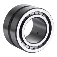
Full complement cylindrical roller bearings
Design specification
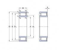
Main dimensions
Main dimensions of full complement cylindrical roller bearings are specified in the dimension tables and they are in accordance with the international standards ISO 15 with the exception of the NNF 50 range, where the width of the outer ring is 1 mm smaller. All other dimensions are the same.
Structure
Full complement cylindrical roller bearings have three main parts – the inner ring equipped with flanges, cylindrical rollers and the outer ring. According to the arrangement, snap rings, angle ring or seals are added.
The following constructions are most common
NCF
These are the most common full complement cylindrical roller bearings. The inner ring has two flanges, the outer ring has one flange on one side and a snap ring, which keeps the bearing assembled on the other side. NCF bearings are able to carry axial load from one side a they are able to accommodate certain minor axial displacement of the shaft. The permissible values for this displacement are in the dimension tables.
Double row bearings
Double row full complement cylindrical roller bearings are all supplied with a lubrication groove with holes in the outer ring, which enables full lubrication access into the rolling space of each row of cylindrical rollers. The inner ring of the NNC, NNCL and NNCF design has three guiding flanges to ensure guiding accuracy of cylindrical rollers. They differentiate by the number of guiding flanges and snap rings in the outer ring. These components stop the rolling elements from falling out.
NNC
One side of outer ring is equipped with guiding flange, the other side has snap ring to keep the cylindrical rollers in place. These bearings can carry the axial load in both directions.
NNCL
NNCL bearings have the flangeless outer ring therefore certain axial bearing rings displacement against each other is accommodated.
NNCF
The outer ring has one flange and one snap ring. These components accommodate axial load transfer in one direction and also certain shaft displacement of the housing.
NNF
NNF bearings are produced with guiding flanges in the two-piece inner ring, which is held together by a retaining ring. The outer ring has a guiding flange. These bearings can also carry the axial load in both directions and as per bigger distance between individual rows of cylindrical rollers, they can transfer a tilting moments.
The outer ring of an NNF bearing is 1 mm narrower than the inner ring and has two snap ring grooves. These bearings are supplied as standard with seals on both sides and the inner space is filled with grease to enable the bearing operation in standard working conditions up to 110°C.
Tolerance
Full complement cylindrical roller bearings are produced as standard in tolerance class P0. Production of bearings with higher tolerance should be discussed in advance. Dimension tolerances are in accordance with the international standards and are stated in ISO 492 standard.
NNC design is the exception to above as it comes in various outer ring widths. They can vary up to double of the tolerance.
Radial clearance
Full complement cylindrical roller bearings are produced and supplied as standard in standard radial clearance or alternatively in C3 clearance. The radial clearance C2 (smaller than standard clearance), alternatively C4, C5 (greater than standard and C3 clearance). Radial clearance values are in accordance with the ISO 5753 standard. These values are applicable for manufactured and unassembled bearing.
Stabilisation for operation at higher temperature
For operating temperature higher than 120°C specially stabilized bearings with individually heat-treated components to ensure dimension and shape stability under long-term exposure to temperatures ranging from 150°C to 400°C (S0, S1, S2, S3 and S4) are supplied. Delivery of stabilized bearings should be discussed in advance.
Suffixes
This list shows suffixes for deliverable designs which differ from the standard:
2NR two separately included snap rings type WRE (bearing type NNF)
BR burnished
C3 radial internal clearance higher than CN*1
C4 radial internal clearance higher than C3*1
C5 radial internal clearance higher than C4*1
HA1 inner ring and outer ring from case hardening steel*1
HB1 inner ring and outer ring from bainite hardened*1
P6 dimensional and running tolerance less than PN*1
P5 dimensional and running tolerance less than P6*1
PH phosphated*1
PP sealing rings on both sides
S0 heat stabilized up to 150°C
S1 heat stabilized up to 200°C
S2 heat stabilized up to 250°C
V full complement
VH full complement, self-retaining set of rollers


