Features of the Crossed Roller Ring

Structure and Features
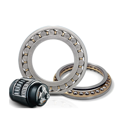
With the Cross-Roller Ring, cylindrical rollers are arranged with each roller perpendicular to the adjacent roller, in a 90° V groove, separated from each other by a spacer retainer. This design allows just one bearing to receive loads in all directions including radial, axial and moment loads. Since the Cross-Roller Ring achieves high rigidity despite the minimum possible dimensions of the inner and outer rings, it is optimal for applications such as joints and swiveling units of industrial robots, swiveling tables of machining centers, rotary units of manipulators, precision rotary tables, medical equipment, measuring instruments and IC manufacturing machines.
High Rotation Accuracy
The spacer retainer fitting among cross-arrayed rollers prevents rollers from skewing and the rotational torque from increasing due to friction between rollers. Unlike conventional types using steel sheet retainers, the Cross-Roller Ring does not cause unilateral contact of roller or seize. Thus, even under a preload, the Cross-Roller Ring provides stable rotation.
Since the inner and outer rings are designed to be separable, the bearing clearance can be adjusted.
In addition, a preload can be applied. These features enable accurate rotation.
Easy Handling
The inner and outer rings, which are separable, are secured to the Cross-Roller Ring body after being installed with rollers and spacer retainers in order to prevent the rings from separating from each other. Thus, it is easy to handle the rings when installing the Cross-Roller Ring.
Skewing Prevention
The spacer retainer keeps rollers in their proper position, thereby preventing them from skewing(tilted rollers). This eliminates friction between rollers, and therefore secures a stable rotational torque.
Increased Rigidity (Three to Four Times Greater than the Conventional Type) Unlike the thin angular ball bearings installed in double rows, the cross array of rollers allows a single Cross-Roller Ring unit to receive loads in all directions, increasing the rigidity to three to four times greater than the conventional type.

Large Load Capacity
(1) Compared with conventional steel sheet retainers, the spacer retainer allows a longer effective
contact length of each roller, thus signifi cantly increasing the load capacity. The spacer retainer guides rollers by supporting them over the entire length of each roller, whereas the conventional type of retainer supports them only at a point at the center of each roller. Such one-point contact cannot suffi ciently prevent skewing.

(2) In conventional types, the loaded areas are asymmetrical between the outer ring and the inner ring sides around the roller longitudinal axis. The greater the applied load is, the greater the moment becomes, leading end-face contact to occur. This causes frictional resistance, which hinders smooth rotation and quickens wear.

Types of the Cross-Roller Ring
Types and Features
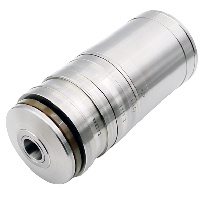
Model RU (Integrated Inner/Outer Ring Type)
Since holes are drilled for mounting, the need for a presser fl ange and a housing is eliminated. Also, owing to the integrated inner/outer ring type stryucture with washer, there is almost no effect from installation on performance, allowing stable rotational accuracy and torque to be obtained. Can be used for both outer and inner ring rotation.

Model RB (Separable Outer Ring Type for Inner Ring Rotation)
Cross-Roller Ring basic type, with a separable outer ring, and an inner ring integrated with the main body.It is used in locations where the rotational accuracy of the inner ring is required. It is used, for example, in the swivel portions of index tables of machine tools.

Model RE (Two-piece Inner Ring Type for Outer Ring Rotation)
Main dimensions are the same as model RB. This model is used in locations where the rotational accuracy of the outer ring is required.

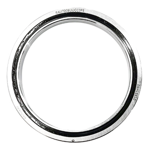
Model RA (Separable Outer Ring Type for Inner Ring Rotation)
A compact type similar to model RB with the thinnest possible inner and outer rings. Optimal for locations requiring a light-weight and compact design such as the swivel portions of robots and manipulators.

Selecting a Cross-Roller Ring
The following diagram shows a typical procedure for selecting a Cross-Roller Ring.

Fit
Fitting of Models RU
Fitting for model RU is typically not required. However, for fi tting requiring positioning accuracy, h7 and H7 are recommended.
Fitting of Models RB, RE and RA
For the fi tting of models RB, RE and RA, we recommend using the combinations indicated in Table1 .
Table1 Fitting of Models RB, RE and RA

Fitting of the USP-grade
For the fi tting of the USP-grade series of models RB and RE, we recommend using the combinations
indicated in Table2 .
Table2 Fitting of the USP-grade

Fitting of Model RA-C
Since model RA-C is thin and its outer ring is split in one position, it is considerably affected by fit.
We recommend measuring the inner and outer diameters of the bearing and applying a slight interference
fit to match the diameters.
Example of Assembly
Fig.2 and Fig.3 show examples of installing the Cross-Roller Ring.

Model Number Coding
Model number confi gurations differ depending on the model features. Refer to the corresponding
sample model number confi guration.
Cross roller rings with integrated inner and outer rings.
Model RU

Models RB, RE, RA and RA-C

Handling
(1) The separable inner or outer ring is fastened in place using special rivets, bolts or nuts when
delivered. When installing it to the system, do not disassemble it. Also, erroneously installing the
spacer retainer will signifi cantly affect the rotational performance of the system. Do not disassemble
the bearing.
(2) The matching mark of the inner or outer ring may be slightly misaligned when delivered. In that
case, loosen the bolts that secure the inner or outer ring, and correct the alignment using a plastic
hammer or the like, before installing it to the housing. (Let the securing rivets follow the housing.)
(3) When installing or removing the Cross-Roller Ring, do not apply force to the fi xing rivets or the
bolts.
(4) When mounting the presser fl ange, take into account the dimensional tolerances of the parts so
that the fl ange fi rmly holds the inner and outer ring from the side.
(5) Dropping or hitting the Cross-Roller Ring may damage it. Giving an impact force to the bushing
could also cause damage even if the product looks intact.
Procedure for Assembly
When assembling the Cross-Roller Ring, follow the steps below.
[Preparations before assembly]
(1) Thoroughly clean the housing and other assembly parts, and make sure there are no burrs.
(2) Loosen the bolts that prevent separation of the Cross-Roller Ring.
(3) If the two divided parts of the outer or inner ring are misaligned at the joints, correct the misalignment
by gently hitting the ring with a plastic hammer or the like, and then install it. (For a type secured with rivets, install it as-is.)
[Installing the Cross-Roller Ring into the Housing or onto the Shaft]
Since the Cross-Roller Ring is a thin bearing, it tends to tilt as it is installed. To prevent it, gradually drive the Cross-Roller Ring into the housing or onto the shaft by gently hitting it with a plastic hammer while keeping it horizontal. Be sure to keep hammering it with much care until you hear it fully contact the reference surface.
Note) When inserting the inner ring, hammer the inner ring. When inserting the outer ring, hammer the outer ring.
[Assembly directions for RU]
Model RU has insertion holes for installing rollers in the outer ring. (Filler plugs are attached.) Position the
mounting direction so that the fi ller plugs do not overlap with the area under maximum load. (The periphery
of the plugged section is slightly recessed, and a fi xing pin is driven into its side.)
[Assembly directions for RA-C]
The outer ring of model RA-C has a slit for installing rollers. Position the mounting direction so
that the split section does not overlap with the area under maximum load. (The split section has two
small holes on the side marked with the product name.)
[Attaching the Presser Flange]
(1) Fit the presser fl ange to the single piece ring (inner ring on models RB/RA , outer ring on model
RE). In case of model RU, fi t the presser fl ange to the rotational axis side.
(2) Place the presser fl ange onto the Cross-Roller Ring. Rock the fl ange several times to match the
bolt holes. Also in case of model RU, rock the fl ange several times to match the bolt holes.
(3) Insert the presser bolts into the holes. Manually turn the bolts and make sure they do not show
skewing caused by misalignment of the holes.
(4) Fasten the presser bolts in three to four steps from loose to fully fastened by tightening the bolts
in a diamond pattern, as shown in Fig.1. When tightening the separated inner or outer ring, reciprocating
the single piece outer or inner ring approximately four to fi ve times (about 90°) will
correct misalignment between the ring and the body.

Tightening Sequence
Lubrication
(1) Since each Cross-Roller Ring unit contains high-quality lithium soap group grease No. 2, you
can start using the product without replenishing grease. However, the product requires regular
lubrication since it has a smaller internal space than ordinary roller bearings and because the
rollers need frequent lubrication due to their rolling contact structure.
To replenish grease, it is necessary to secure greasing holes that lead to the oil grooves formed
on the inner and outer rings. As for the lubrication interval, normally replenish grease of the
same group so that it is distributed throughout the interior of the bearing at least every six to
twelve months.
When the bearing is fi lled up with grease, the initial rotational torque temporarily increases. However,
surplus grease will run off of the seals and the torque will return to the normal level in a
short period. The thin type does not have an oil groove. Secure an oil groove inside the housing
for lubrication.
(2) Do not mix greases with different physical properties.
(3) In locations exposed to constant vibrations or in special environments such as clean rooms,
vacuum and low/high temperature, normal lubricants may not be used. Contact Monton for details.
(4) When planning to use a special lubricant, contact Monton before using it.
Precautions on Use
(1) Entrance of foreign material may cause damage to the ball circulating path or functional loss.
Prevent foreign material, such as dust or cutting chips, from entering the system.
(2) Contact Monton if you desire to use the product at a temperature of 80.